Rolled reinforcing spiral of the periodic profile of class В500С
for reinforcement of reinforced concrete structures. Technical specifications
Foreword
The standard legitimizes the use of spiral reinforcing bars, characterized by a reduced metal capacity while maintaining the strength of the reinforced concrete structure due to a significantly larger relative surface of the crushing than in the rolled metal, for example, according to GOST R 52544-2006.
It is known that, both for technical reasons and for the effectiveness of the application, cold-cured fittings are preferable to hot-rolled and thermomechanical reinforced fittings.
One of the obstacles for the mass introduction of cold-formed reinforcement in the building
The production is reduced compared to the A500C class valve by 4.8%
resistance. This consideration does not seem justified.
For cold-cured fixtures, the design resistance should be equated with the hot-rolled reinforcement, which will make it impossible to recalculate the design documentation [1].
About the standard
1 DEVELOPMENT INCERCOM together with ART-MODERNSRL.
2 INNOVATION INCERCOM.
3 APPROVED AND ENTRY INTO FORCE Order of the Ministry No. ___ of ____
4 INTRODUCED FOR THE FIRST TIME
1. Area of use
This standard applies to spiral reinforcing bars of periodic profiles of classes СА500С and СВ500С, intended for reinforcement of reinforced concrete structures.
2. Normative references
Normative references to the following standards are used in this standard:
GOST 7566-94 Metal products. Acceptance, marking, packaging, transportation and storage
GOST 10884-94 Reinforced steel thermomechanically reinforced for reinforced concrete structures. Technical specifications
GOST 10922-90 Reinforcement and embedded products welded, joints of welded reinforcement and embedded products of reinforced concrete structures. General specifications
GOST 12004-81 Steel reinforcing. Methods of tensile testing
Steel alloys and high alloy. Methods for determination of molybdenum
GOST 12359-99 (ISO 4945-77) Carbon steels, alloyed and highly alloyed. Methods for determination of nitrogen
GOST 14019-2003 (ISO 7438: 1985) Metallic materials. Bending test method
GOST 14098-91 Joints of welded reinforcement and embedded products of reinforced concrete structures. Types, designs and sizes
Rolled ferrous metals. Terms and definitions of surface defects
Carbon steel and cast iron, unalloyed. General requirements for analysis methods
Carbon steel and cast iron, unalloyed. Methods for determination of total carbon and graphite
Carbon steel and cast iron, unalloyed. Methods for determination of sulfur
Carbon steel and cast iron, unalloyed. Methods for determination of phosphorus
GOST 22536.5-87 (ISO 629-82) Carbon steel and cast iron, non-alloy. Methods for the determination of manganese
Carbon steel and cast iron, unalloyed. Methods for the determination of chromium
Carbon steel and cast iron, non-alloy. Methods for determination of copper
Carbon steel and cast iron, unalloyed. Methods for the determination of nickel
Carbon steel and cast iron, unalloyed. Methods for determination of vanadium
GOST 27809-95 Cast iron and steel. Methods of spectrographic analysis
GOST 28473-90 Cast iron, steel, ferroalloys, chromium, manganese, metallic. General requirements for methods of chemical analysis
GOST 29273-92 (ISO 581-80) Weldability. Definition
OST 14-1-34-90 Statistical acceptance control of metal products according to the correlation relationship between the parameters.
3. Terms and definitions
In this standard, the following terms are used with the corresponding definitions:
3.1 Spiral bars of periodic profile: Rods, the cross section of which is two or three triangles with rounded bases connected by peaks, the places of their connection being planes provided with periodic convexities of arbitrary shape. The spiral rolling profile is obtained by rotating and translating this section relative to the rectilinear axis of the rod.
3.2 Reinforcing bars of nominal diameter d, mm: Reinforcing bars inscribed in an imaginary cylinder whose diameter, d taking into account the permissible deviations, corresponds to the diameter of the assortment according to Table 1.
3.3 Nominal cross-sectional area Fk, mm2: The cross-sectional area of the rolling, equal to the cross-sectional area of a round smooth rod of the same nominal diameter.
3.4 Actual cross-sectional area F, mm2: cross-sectional area of rolled metal, determined by formula
F = P / l • Υ, where (1)
P is the mass of the rod,
l-section,
Υ is the specific gravity of the rod material.
3.5 Elements of the periodic profile of reinforcing bars (see Appendix A):
3.5.1 Rib: Continuous longitudinal spiral projection, the cross-section of which is close to a triangular one, formed along the axis of reinforcing bars during its rolling.
3.5.2 Jumper: the central part of the rod connecting the vertices of the ribs, each of whose surfaces is a flat spiral, provided with projections of arbitrary shape.
3.6 Geometric parameters of the periodic profile of reinforcing bars:
3.6.1 Diameter d: distance between the tops of the ribs passing through the center of the cross-section of the rolled stock, measured along the rolling axis.
3.6.2 Thickness of the web, h:
- for rolling type 1- the distance between the surfaces of the bridge, measured perpendicular to the rolling axis, without taking into account the protrusions on them;
- for rolling type 2 – the diameter of the cylinder inscribed in the space between the surfaces of the bridge, without taking into account the protrusions on them.
3.6.3 Jumper width b, mm: The distance between the intersection lines of the jumper plane with the sides of adjacent ribs, measured perpendicular to the rolling axis.
3.6.4 Angle at the vertex of the rib α: Angle between the sides of the edge measured in cross section, perpendicular to the roll.
3.6.5 Spiral T: the distance between the vertices of adjacent ribs, measured along the rolling axis.
3.6.6 Height of the protrusion, mm: Size from the top of the ledge to its base.
3.6.7 Relative boundary crumple edge of the periodic profile fR: The product of the number of ribs by the height of the rib and the length of the helix that passes through the middle of the ribs in the length of one step, referred to the product of the circumference of the nominal diameter by the spiral pitch. For rolling type 1, this value is
fR =3,14 х (d – t) xT / 3,13 xbxT = (d – t) / b = (d – t) / 0,3d.(2)
For rolling type 2, which has 3 ribs,
fR = 1,5 х (d – t) / 0,3d. (3)
4. Classification and assortment
4.1 Reinforcing bars are divided according to the production method into classes:
CA500C-hot-rolled without further processing or thermomechanically hardened in the rolling flow,
СВ500С – mechanically strengthened in the cold state (cold-deformed);
In the class designation:
C – spiral reinforcing bars;
A – hot-rolled or thermomechanically reinforced reinforcing bars;
B – cold-formed reinforcing bars;
С – welded reinforcing bar;
500 – yield strength not less than 500 N / mm2.
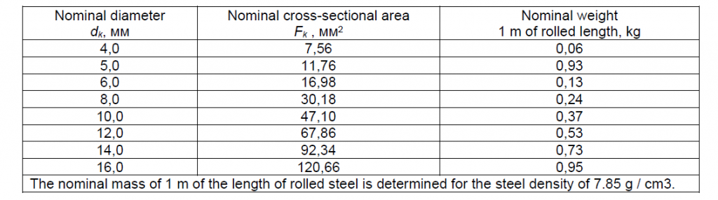
4.2 The nominal diameter, cross-sectional area and mass of 1 m of rolled length shall comply with the values given in Table 1.
Table 1 – Nominal diameter, cross-sectional area and mass of 1 m length of reinforcing bars
4.3 The periodic profile of the reinforcing bar shall consist of two or three spiral rows of ribs having a cross-sectional shape approximating a triangular cross-section and a bridge connecting the longitudinal ribs in one piece.
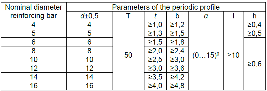
The values of the parameters of the periodic profile and its relative crumple area fR must meet the requirements set forth in Table 2.
Table 2 – Parameters of the periodic profile of reinforcing bars
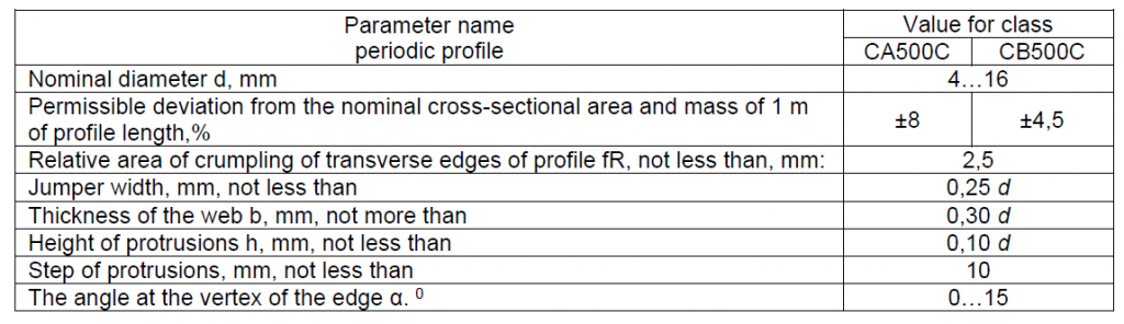
The configuration of the periodic profile is in accordance with Figure A.1 and Table A.1 (see Appendix A) and the general profile requirements for Table 2.
Upon agreement with the customer, the delivery of reinforcing bars with the configuration of the periodic profile, which differs from the requirements of Appendix A, is allowed provided that the properties of rolled products are in accordance with the requirements of this standard.
4.4 Reinforcing bars are manufactured:
- for CA500C class with nominal diameter:
from 6 to 8 mm inclusive – in coils or bars; 10 mm and more – in bars;
- for class CB500C – only in bars.
4.5 The bars are manufactured:
- dimensional length (MD) in the range from 3 to 12 m, specified by the customer in the order;
- Unlimited length (ND) in the range from 3 to 12 m, as determined by the manufacturer.
Limit deviations along the length of bars measuring length – plus 100 mm.
4.6 The curvature of the rods shall not exceed 0.6% of the measured length.
4.7 Examples of legend:
Rebar in bars, nominal diameter 12 mm, class СА500С, measuring length (MD) 11700 mm:
Rod 12×11700-CA500C (name of the standard)
Reinforcing bars in coils with a nominal diameter of 8 mm, class В500С:
Motok 8-SV500S (name of the standard)
5. Technical requirements
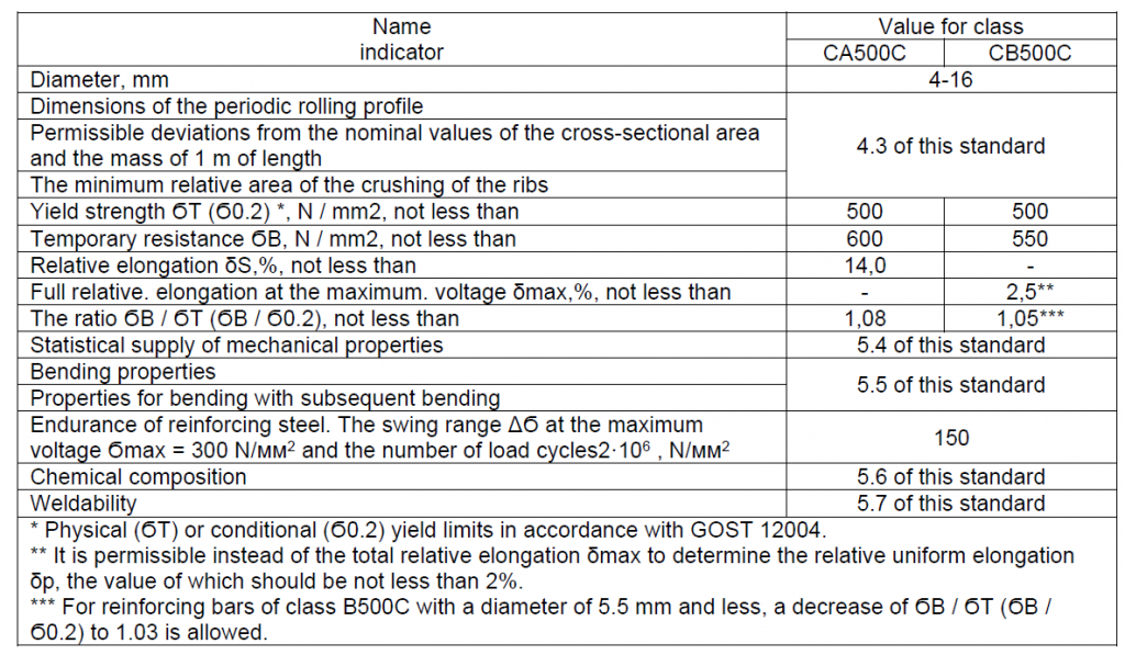
5.1 The properties of reinforcing bars shall comply with the standards set forth in Table 3.
Table 3 – Properties of reinforcing bars
5.2 Reinforcing bars of the class CA500C are supplied hot-rolled without further processing and are heat-mechanically strengthened in the rolling stream, class CB500C – in the cold-deformed state.
5.3 On the surface of reinforcing bars are not allowed:
- cracks;
- Sunsets, captivity and shell, worsening its characteristics.
Classification of surface defects – according to GOST 21014.
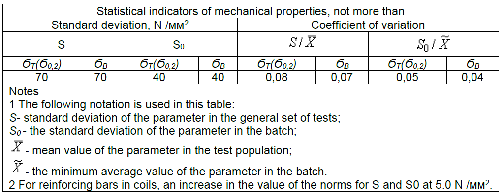
5.4 Statistical indicators of the temporary resistance ϬBy and the yield point ϬT (Ϭ0.2), indicated in Table 3, in each lot should be not less than 0.95.
5.5 Rebar should withstand one of the following tests:
- for a single bend in the cold state to an angle of 180 ° around the mandrel with a diameter equal to 3dK;
- to bend to an angle of at least 90 °, followed by a bend to an angle of at least 20 °.
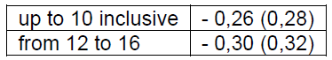
The diameters of the mandrel for bending tests with subsequent bending shall be as specified in Table 4.
Table 4 – Diameters of the mandrel for testing reinforcing bars for bending with subsequent bending

5.6 The chemical composition of the steel and the value of the carbon equivalent shall be as specified in Table 5.
Table 5 – Chemical composition of steel and carbon equivalent values
5.7 The weldability of reinforcing bars is provided by the chemical composition of the steel and the technology of its manufacture and is controlled in accordance with Appendix B.
5.7.1 To ensure the required strength of welded joints of thermomechanically strengthened reinforcing bar (in parentheses – for finished rolled products), the carbon equivalent of C eq should be,%, not less than, for rolling with a nominal diameter, mm
5.8 Statistical indicators of temporary resistanceϬB and yield stress ϬT (Ϭ0.2) of reinforcing bars must meet the requirements of Table 6.
The procedure for determining the statistical indicators of rolled products is given in Appendix B.
Table 6 Statistical indicators of the mechanical properties of reinforcing bars
5.9 At the consumer’s request, the endurance of the rolled product shall comply with the requirements of Table 3 with verification according to the methodology of Appendix G.
6. Basic data for the design of reinforced concrete structures
6.1 Calculation and design of reinforced concrete structures using cold-formed rolled products should be carried out in accordance with the requirements of SNiP 2.03.01, SP 52-101-2003
6.2 For the normative tensile strength “Rsn” of rolled products, the deflection value of the conditional yield stress “s0.2”, ie, 500 N / mm2.
6.3 The design tensile strength “Rs” and “Rs, ser” is determined by dividing the standard resistance “Rsn” by the safety factor of the “gs” armature, taken equal to 1.15 when calculating the structures for the limiting states of the first group and 1.0 for the second group. (SP 52-101-2003 recommends accepting a reliability factor for a valve of class B500 C when calculating the limit states of the first group-1.2, because it applies to all cold-formed reinforcement, including a wire of class Bp-1 (GOST 6727), in which the mass 1 meter of length is less than the nominal length by more than 7%).
6.4 The calculated resistance of the rolled steel used as a cross-armature “Rsw” is reduced in comparison with “Rs” by multiplying by the gsi working conditions factors taking into account the features of the rolling operation in the structure. According to 5.2.7. SP the calculated values of the resistance of the transverse reinforcement (clamps and bent rods) Rsw are reduced in comparison with Rs by multiplying by a factor of operating conditions gs1 equal to 0.8, but taking no more than 300 MPa.
6.5 The values of design resistance of rolled products used as welded clamps are further reduced by multiplying by the coefficient of working conditions: gs2 = 0.9, i.e. Rsw = Rs × gs1 × gs2.
6.6 When rolling is used in welded meshes, its design tensile strength is reduced by multiplying by an operating factor of gs10 equal to 0.95 for an unreinforced (welded) shear strength of the welded joint at the shear and 0.90 for the normalized strength of the welded joint at the shear.
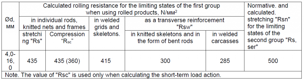
6.7 The values of the standard and design rolling resistance are shown in Table 4.
6.8 The design resistance in appropriate cases should be multiplied by the factor of the operating conditions of the reinforcement according to Table. 24 SNIP 2.03.01-84x) as for a wire of class Bp-1.
6.9 The modulus of elasticity of rolled products according to TU14-1-5552-2007 is taken to be 2.0 x 10⁵ MPa.
6.10 Calculation of elements of reinforced concrete structures for the limiting states of the first group.
6.10.1 Calculation of elements of reinforced concrete structures on the marginal states of the first group is carried out in accordance with section 6 of SP 52-101-2003.
6.10.2 Calculation of the strength of the normal cross-sections for ultimate forces shall be carried out in accordance with 6.2.5-6.2.8 of SP 52-101-2003.
6.10.3 Calculation of the strength of normal sections of bent elements is carried out in accordance with 6.2.9-6.2.14 SP 52-101-2003.
6.10.4 Calculation of the strength of eccentrically compressed elements is carried out in accordance with 6.2.15-6.2.18 of SP 52-101-2003.
6.10.5 Calculation of the strength of centrally stretched elements is carried out in accordance with 6.2.19 of SP 52-101-2003.
6.10.6 Calculation of the strength of eccentrically stretched elements is carried out in accordance with 6.2.20 of SP 52-101-2003.
6.10.7 Calculation of the strength of normal sections on the basis of a nonlinear deformation model is carried out in accordance with 6.2.21-6.2.31 SP 52-101-2003.
6.10.8 Calculation of the strength of reinforced concrete elements under the action of transverse forces shall be carried out in accordance with 6.2.32-6.2.35 of SP 52-101-2003.
6.10.9 Calculation of reinforced concrete elements along the strip between inclined sections is carried out in accordance with 6.2.33-6.2.34 of SP 52-101-2003.
6.10.10 Calculation of reinforced concrete elements along oblique cross sections for the action of moments is carried out in accordance with 6.2.35 of SP 52-101-2003.
6.10.11 Calculation of the strength of reinforced concrete elements under the action of torque is carried out in accordance with 6.2.36-6.2.42 SP 52-101-2003.
6.10.12 The calculation of the joint action of the twisting and bending moments is carried out in accordance with 6.2.39-6.2.40 of SP 52-101-2003.
6.10.13 Calculation of reinforced concrete elements for the joint action of torque and shearing force shall be carried out in accordance with 6.2.41-6.2.42 of SP 52-101-2003.
6.10.14 Calculation of reinforced concrete elements for local compression is carried out in accordance with 6.2.43-6.2.45 of SP 52-101-2003.
6.10.15 Calculation of reinforced concrete elements for punching shall be carried out in accordance with 6.2.46-6.2.48 of SP 52-101-2003.
6.10.16 Calculation of reinforced concrete elements for the pushing under the action of concentrated force and bending moment is carried out in accordance with 6.2.49-6.2.52 of SP 52-101-2003.
Table 7 Normative and calculated resistance of rolling CB500C
6.11 Calculation of elements of reinforced concrete structures for the limiting states of the second group.
6.11.1 Calculation of elements of reinforced concrete structures on the marginal states of the second group is carried out in accordance with section 7 of SP 52-101-2003.
6.11.2 Calculation of reinforced concrete elements for the opening of cracks shall be carried out according to clauses 7.2.1-7.2.4 of SP 52-101-2003.
6.11.3 The moment of formation of cracks normal to the longitudinal axis of the element is determined according to 7.2.5-7.2.11 of SP 52-101-2003.
6.11.4 Calculation of the crack opening width, normal to the longitudinal axis of the element, is carried out according to clauses 7.2.12-7.2.14 of SP 52-101-2003.
6.11.5 Calculation of elements of reinforced concrete structures for deformations is carried out in accordance with paragraph 7.3 of SP 52-101-2003.
6.11.6 Calculation of elements of reinforced concrete structures for deflection is carried out in accordance with 7.3.3-7.3.6 of SP 52-101-2003.
6.11.7 The curvature of the reinforced concrete elements is determined in accordance with 7.3.7-7.3.9 of SP 52-101-2003.
6.11.8 The rigidity of reinforced concrete elements in the area without cracks in the stretched zone shall be determined in accordance with 7.3.10-7.3.15 of SP 52-101-2003.
6.11.9 Curvature of reinforced concrete elements on the basis of a nonlinear deformation model is determined in accordance with 7.3.16 of SP 52-101-2003.
7. Production of works
7.1 Reinforcing elements and products made of B500C class products shall comply with the requirements of the design and technological documentation containing instructions on the manufacture of elements and products at all stages of the production process.
7.2 Edging of reinforcing bars should be carried out in the same way as for cutting wires of class Bp-1 in accordance with GOST 6727-80. At the same time, the depth of the trail from the jaws of the correct drum should not allow more than 25% of the height of the protrusions of the periodic profile.
7.3 Cross-shaped joints of rolled products in welded products, as a rule, should be carried out by spot spot welding (types K1 and K2 according to GOST 14098-91). . Welding with a consumable electrode in a protective gas environment is allowed.
7.3.1 The technology, equipment, design and dimensions of welded joints in contact spot welding are the same as for wire of class Bp-1 according to RTM 393-94 and GOST 14098-91.
7.3.2 Parameters of contact spot welding modes should be assigned depending on the class of reinforcement of smaller diameter, using the technique described in par. 4.1.1 – 4.1.19 RTM 393-94.
7.3.3 When welding joints with bars made of reinforcement of classes Вр-1, А240, А400 and А500, the relative sediment values (h / dn according to GOST 14098-91) should be taken depending on the reinforcement of smaller diameter, guided by the data of Table 2 of GOST 14098- 91 and Table 4.1 RTMs 393-94.
In all cases when welding cold-rolled steel, the relative draft should not exceed 0.5.
7.4 When connecting cold-formed rolled products with a diameter of 10 and 12.0 mm, in addition to contact-spot welding, other welding methods may be used:
- cross-shaped joints with working rods from cold-formed rolled products with non-standardized strength of welded joints in structures intended for operation in conditions of positive temperatures (heated rooms) may be performed with arc stitches (K3 according to GOST 14098-91) according to the technology described in p. 4.2.1 – 4.2.9 RTM 393-94. Arc sticks in joints with reinforcement of class А400 (А-III) from steel grade 35ГС are not allowed;
- contact welding of butt-end joints should be carried out by a continuous reflow method without preheating at the regimes given in 4.3.1 to 4.3.16 RTM 393-94.
- Butt joints of rolled products can be made by manual arc welding with long seams with paired strips (C 22) or lap (C 23) according to GOST 14098-91. The length of the lining or lapping should be at least 8 diameters of the connecting rods. Welding technology – as for valves of A-IIIC class according to RTM 393-94 (items 6.17.4 – 6.17.10).
7.5 When welding with a consumable electrode in a shielding gas environment, a steel-welded copper-plated copper wire according to GOST 2246 of grade 08G2S with a nominal diameter of 1.2-1.6 mm should be used as a melting electrode. As a shielding gas, a mixture of argon and carbon dioxide (80% Ar + 20% CO2) should be used according to TU 2114-002-05015259-97.
7.6 Welding in a protective gas environment with a consumable electrode should be carried out in the following modes:
- wire feed speed of 8-12 m / min;
- voltage on the arc 25-36 V;
- Protective gas consumption (80% Ar + 20% CO2) – 10 … 15 l / min.
- the shape and extent of the welded seam is determined by the required strength of the welded joint.
7.7 When welding cruciform joints on contact-point machines, the strength of the welded joint at the cut must be not less than 50% of the conditional yield strength of the rolled product.
7.8 When welding with a consumable electrode in a shielding gas environment, cruciform connections with standardized strength shall have weld seams on both sides of the rod, and with mounting strength on one side.
7.9 Lap joints of rolled products should be flank seams only with a consumable electrode in a protective gas environment.
7.10 The strength of the lap joints shall be not less than 30% of the nominal yield strength.
7.11 The strength of the cruciform joints for breaking (weakening) should be not less than the conditional yield point.
7.12 Cross-shaped welded joints of rolled products shall withstand the bending test without the appearance of kinks, delaminations and cracks visible without the use of magnifying devices.
7.13 Weld the clamps using flange seams in accordance with Fig. 5.
7.14 General requirements for quality control of welded joints must comply with the provisions of GOST 10922-90 and RTM 393-94 to reinforcing wire.
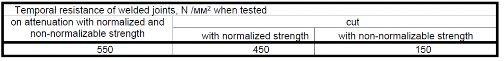
7.15 Welded joints in mechanical weakening and shearing tests shall have minimum values of the temporary resistance not lower than those given in Table 7.
7.16 Welded joints with non-standard (mounting) shear strength may not be tested, as they must provide only the required relative positioning of the rods in the reinforcement products during transport and concreting. Evaluation of their quality can be carried out by the value of the relative precipitation.
Table 8 Temporal resistance of welded joints
7.17 The test of welded cruciform joints of the armature for bending shall be carried out in accordance with GOST 14019. In the bending test, the welded transverse rod shall be located in the stretched zone.
7.18 The curvature of the rolled bars after straightening should not exceed 0.6% of the controlled length.
7.19 Rent of class В500С is not allowed to be used as mounting loops and anchors of embedded products without experimental justification.
7.20 Structural requirements for reinforced concrete elements reinforced with rolled products according to TU 14-1-5552-2007, according to section 8 of SP 52-101-2003 and section 5 of TSN 102-00.
7.21 When reinforcing reinforced concrete structures by rolling according to TU 14-1-5552-2007, a protective layer of concrete is installed in accordance with 8.3.1-8.3.2 SP 52-101-2003.
7.21.1 The minimum distance between the reinforcement bars is established in accordance with 8.3.3 of SP 52-101-2003.
7.21.2 Longitudinal and transverse reinforcement of reinforced concrete elements with the above-mentioned rolled products should be carried out in accordance with 8.3.4- 8.3.17 SP 52-101-2003.
7.21.3 Anchorage of rolled metal is prescribed in accordance with 8.3.18-8.3.25 of SP 52-101-2003.
7.21.4 The joining of the rods is carried out in accordance with 8.3.26 to 8.3.29 of SP 52-101-2003.
7.21.5 When using bent rolled products, the instructions of 8.3.30 SP 52-101-2003 should be followed.
8. Acceptance rules
8.1 General acceptance rules – according to GOST 7566.
8.2 Acceptance of control from the manufacturer
8.2.1 Rebar from the manufacturer is accepted in lots with the following characteristics:
- yield point;
- temporary resistance;
- the relative elongation;
- bending properties;
- cross-sectional area and mass of 1 m length;
- the dimensions of the periodic profile and the relative area of the crumpling of the transverse edges of the periodic profile;
- chemical composition and carbon equivalent;
- surface quality;
- Curvature of rods.
8.2.2 The batch shall consist of reinforcing bars of one nominal diameter, one delivery state, one melting bucket and shall be documented with one quality document.
The lot weight should not be more than 70 tons.
It is allowed to increase the mass of the A500C class batch to the weight of the smelting ladle.
8.2.3 Each lot is selected:
- for the control of chemical composition – one sample;
- to control the quality of the surface, the geometric dimensions of the profile and the mass of 1 m of length – 2 samples;
- for tensile tests – 2 samples;
- for bending or bending tests with a bend – 2 samples.
8.2.4 Each separate test result shall satisfy the requirements of Section 5.
8.2.5 In case of receiving unsatisfactory test results, at least one of the indicators repeated tests are carried out on a doubled number of samples. The results of repeated tests are final.
8.3 The control of endurance and weldability of reinforcing bars shall be carried out in accordance with Annexes D and B.
8.4 Each batch of reinforcing bars must be accompanied by a document on quality, issued in accordance with the requirements of GOST 7566.
In the document on quality for reinforcing bars indicate:
- nominal diameter;
- Class of reinforcing bars and designation of this standard;
- the mass fraction (smelting) in the steel of the chemical elements given in 5.6 (Table 5) and 7.9;
- time resistance ϬB;
- yield strength ϬT (Ϭ0.2);
- the relative elongation δS or the total elongation δmax;
- results of a cold bending test or bending test followed by a bend.
At the consumer’s request, the quality document indicates the statistical indices of the strength properties-the minimum average values in each batch of yield strength, the time resistance and their standard deviation S0, the endurance and weldability data.
8.5 Entrance control at the consumer
8.5.1 Each lot of reinforcing bar is subjected to the entrance control of the consumer.
8.5.2 To check the quality of the surface, the geometric parameters and the mass of 1 m of the length of the rolled product, as well as tensile, bending or bending tests with bending, one sample is taken.
8.5.3 For reinforcing bars supplied with the indication in the document on the quality of statistical indicators of mechanical properties, it is not allowed to test tensile, bend or flexural bends.
8.5.3.1 In case of disagreement in the evaluation of product quality, the control of mechanical properties shall be carried out in accordance with Annex B.
9. Test methods
9.1 The quality of the surface of the reinforcing bar is checked without the use of magnifying devices.
9.2 For tensile tests, reinforcing bars are used in the delivery state or after straightening.
Tensile tests with the definition of T (Ϭ0.2), ϬB, δS and δmax are carried out in accordance with GOST 12004.
9.3 Determination of statistical indicators of the variability of the mechanical properties of reinforcing bars in the general population and in each lot shall be carried out in accordance with Annex B.
9.4 Cold bending tests shall be carried out in accordance with GOST 14019.
9.5 Bend tests with subsequent bending shall be carried out in accordance with GOST 10884.
9.6 Endurance tests are carried out according to the procedure given in Appendix G.
9.7 The geometric parameters of the reinforcing bar shall be checked in accordance with annex E.
9.8 Chemical analysis of steel is carried out according to GOST 12354, GOST 12359, GOST 22536.0 – GOST 22536.3, GOST 28473, GOST 22536.5, GOST 22536.7 – GOST 22536.9, GOST 22536.12, GOST 27809 or other methods that provide the necessary accuracy.
9.9 The carbon equivalent of Sect, given in Table 5, is calculated by the formula
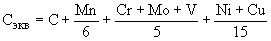
Where C, Mn, Cr, Mo, V, Ni, Cu are the actual mass fractions, respectively, of carbon, manganese, chromium, molybdenum, vanadium, nickel and copper in steel,%.
10. Marking, packaging, transport and storage
10.1 Marking, packaging, transportation and storage of reinforcing bars – according to GOST 7566 with the following additions.
10.2 Marking
10.2.1 Each bundle and every reel of rolled products shall bear a tag indicating:
- a trademark or an abbreviation of the manufacturer;
- The nominal diameter of reinforcing bars, mm;
- class of reinforcing bars;
- designation of this standard;
- batch number.
An example of marking is shown in Figure 1.
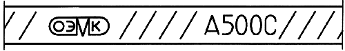
Fig / 1 Example of marking of reinforcing bars of A500C class produced by ART-MODERNSRL
10.2.2 Other types of marking agreed with the customer are allowed.
10. Packaging
10.3.1 General packing rules – according to GOST 7566 with the following additions.
10.3.2 The rods are packed in bundles with a weight of 1.5 to 15 tons. At the request of the consumer, the weight of the bundle may be less than 1.5 tons.
10.3.3 When delivered in coils, each coil shall consist of one piece of reinforcing bar. It is allowed to supply skeins consisting of two lengths, in an amount not exceeding 10% of the batch weight. Weight skelet should be from 0.3 to 1.5 tons.
As agreed by the manufacturer with the consumer, the weight of the hank is from 0.03 to 0.3 tons and from 1.5 to 3.0 tons.
The hammer must be tightly tied. The quantity and scheme of the straps are stipulated in the order or contract.
Appendix A (compulsory)
Types and dimensions of the periodic profile of reinforcing bars
A.1 The configuration, dimensions and limit deviations from the dimensions of the periodic profile of reinforcing bars ensuring compliance with the requirements of Table 2 of this standard are shown in Figure A.1 and in Table A.1.
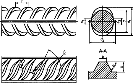
Figure A.1 – Periodic profile of hot-rolled and thermomechanically hardened reinforcing bars
Table A.1 In millimeters
The dimensions for which the maximum deviation is not specified are given for the construction of the caliber and are not checked on the finished profile.
A.3 Quality of reinforcing bars of periodic profile according to Figures A.1-A.3 – in accordance with Table 2.
Appendix B (compulsory)
Method of testing of reinforcing bars for weldability
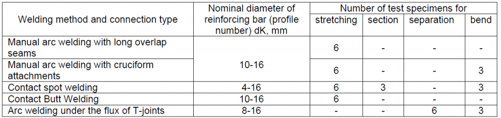
B.1 Control of weldability (suitability for welding) of reinforcing bars is carried out by testing widely used in construction and most influencing the mechanical properties of welded joints in accordance with Table B.1.
Table B.1
B.2 For the production of samples of welded joints, reinforcing bars with the lowest carbon equivalent value, Seq, are used for the annual steel production period preceding the testing.
B.3 The weldability tests shall be subjected to reinforcing bars of minimum, average and maximum diameters from the range produced by the manufacturer. Rebar of each diameter is selected for testing from three randomly chosen melts that meet the requirements of B.2.
B.4 Manufacturing of samples of welded joints
B.4.1 The constructions and dimensions of the connections are the same as for the A-III (A400) valves in accordance with GOST 14098.
B.4.2 The equipment, welding materials, parameters of welding modes and features of welding technology used for manufacturing welded samples shall be the same as for welding of A-III (A400) valves in accordance with the requirements of [1]. When welding samples from cold-worked steel, the process parameters are accepted for welding A-III valves according to [1], but with the following changes:
- Manual arc welding with long seams overlapping (type C23-Re according to GOST 14098) is carried out by applying seams “from the edges to the middle”, with each subsequent seam being superimposed after the complete cooling of the previous one;
- contact butt welding (type C1-Co according to GOST 14098) should be carried out by a continuous reflow method without preheating.
B.4.3 Designs and dimensions of test pieces depending on the type of connection, test methods and diameters of reinforcing bars shall be the same for GOST 10922 as for valves of class A-III (A400).
B.5. The order of testing and evaluation of their results
B.5.1 Tests of welded specimens for tension, shear and separation shall be carried out according to the methods and with the use of the devices specified in GOST 12004 and GOST 10922 for valves of class A-III (A400).
B.5.2 Testing of cruciform specimens for bending is performed around a mandrel with a diameter D of 5dK – with a working rod diameter of up to 12 mm inclusive or 6dK – with a working rod diameter of more than 12 mm. The transverse rod (of smaller diameter) in bending tests should be located in the zone of maximum bending moment (figure B.1). Tests for bending specimens of T-joints of rods with plates are carried out manually with the help of a pipe, which is put on the welded section of the reinforcing bar (Figure B.2).
B.5.3 The tensile test results of the butt joint specimens are considered satisfactory if the failure occurs outside the weld or in the weld region at a time resistance of at least 600 N / mm2 for hot rolled and thermomechanical hardened rolled products and 550 N / mm2 for cold-formed ones. Destruction in the area of the weld joint must be plastic, i.e. characterized by a noticeable narrowing (such as “neck”). Brittle fractures (ie at an angle of 90 ° to the axis of the rod and without visible constriction) are not allowed.
B.5.4 The results of the flexural tests of the compounds of B.5.2 are considered satisfactory if the specimen has not collapsed to a bending angle of 60 ° and no visible cracks have appeared. The detachment of the transverse rod during the tests of cruciform joints made by contact point and manual arc welding is not a defect sign.
B.5.5 The cross-cut test results are considered satisfactory if the shearing force is not less than 0.3ϬT • FK, where ϬT = 500 N / mm2, FK is the nominal cross-sectional area of the thinner bar in the joint, along the axis of which the load is applied tests.
B.5.6 The results of the test for tear joint detachment are considered satisfactory if the obtained values of the time resistance for each tested sample are not less than 500 N / mm2. In this case, the test compounds can be destroyed both in the armature in the area located in the heat-affected zone of welding, and in the zone of fusion of the reinforcing bar with the plate.
B.5.7 Rebar shall be considered weldable if the test results of all tested samples are considered satisfactory in accordance with B.5.3-B.5.6.

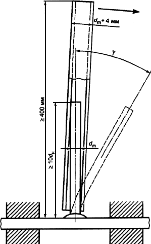
dm- maximum cross-sectional dimension of the tested reinforcing bar
Figure C.1 – Diagram of bend tests for cruciform welds
dm- maximum cross-sectional dimension of the tested reinforcing bar
Figure B.2 – Test scheme for bending T-welds
Appendix C (compulsory)
Requirements for statistical indicators of strength characteristics and methods for their determination
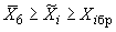
C.1 The manufacturer guarantees to the consumer the average values of the temporary resistance ϬB and the yield strength (physical ϬTypicalϬ0.2) in the general population and the minimum average values of the same indicators in each batch (smelting), the values of which are established from the conditions:

(B.1)
where XiBr are the rejection values of the characteristics ϬT (Ϭ0.2) and ϬB, established by Table 3;
S is the standard deviation of the actual characteristics ϬT (Ϭ0.2) and ϬB in the general set of tests;
S0 is the standard deviation of these characteristics in the batch.
C.2 The required quality indicators of reinforcing bars are ensured by compliance with the technology of production of reinforcing bars when it is mass-produced and controlled in accordance with the requirements of Section 7 of this standard.
C.3 The values and are determined based on the test results and provisions B.6-B.15 of this annex.
C.4 If it is necessary to check the strength characteristics of reinforcing bars by the consumer, and in cases of disagreement in the evaluation of the quality of reinforcing bars, six samples taken from different coils or bars are tested from each lot and the results of these tests are checked for the fulfillment of the conditions for the corresponding characteristics:
(B.2)
Where Xmin is the minimum value of the tested characteristic from the test of six samples;

– the average value of the test characteristic according to the test results of six samples;
Values

and

– according to the document on the quality of this batch of reinforcing bars.
C.5 The minimum values of the relative elongations δS and δmax shall not be less than those given in Table 3 of this standard.
C.6 To determine the statistical indexes of strength characteristics of reinforcing bars (temporary resistance and physical or conditional yield strength), established by this standard, the results of acceptance tests are used.
The conformity of strength characteristics of reinforcing bars to the requirements of this standard is determined on the basis of statistical processing of the results of tests of reinforcing bars, which form a sample from the general set of strength characteristics of reinforcing bars.
Conclusions made on the basis of sampling processing are referred to the whole population.
C.7 The sampling used to determine the statistical indicators should be representative and cover a sufficiently long period of time (at least three months) during which the technological process for the production of this reinforcing bar has not changed.
The number of lots must be at least 50.
C.8 The sample should include the results of control tests of reinforcing bars rolled on one or a group of similar profilers for one method of steelmaking.
C.9 When sampling, it is necessary to observe the conditions for random sampling from each batch.
Evaluation of the anomaly of the test results and verification of sample homogeneity is carried out according to normative documents.
C.10 During the statistical processing of the results of the control tests, the average value of the strength characteristics of reinforcing bars in the sample (the population) is determined, the standard deviation of this characteristic in the sample is Si and its standard deviation in the batch S0, and the standard deviation of the sintering Si.
Values and Determined by regulatory documents.
C.11 The value of S0 is determined by the experimental method or the swing method by the formula

(В.3)
Where

and

are, respectively, the mean and standard deviation of the span distribution for the two batch tests
C.12 The determination of S0 by an experimental method shall be carried out with at least two meltings for each grade of steel, class and rolling profile, by randomly selecting at least 100 samples from each melting.
C.13 Si is determined by the formula

C.14 Stability check and S-wire in accordance with OST 14-1-34.
C.15 The minimum average value of the strength characteristics of reinforcing bars (ϬB, ϬTil or Ϭ0.2) in each batch is determined by formula
(В.5)
C.16 The minimum value of the test results of two samples (n = 2) in each batch to be monitored shall be not less than the value Xmin determined by the formula (B.2).
Appendix D (compulsory)
Method of testing reinforcing bars for endurance
D.1 To determine the suitability of the endurance of reinforcing bars, endurance tests are carried out annually in accordance with Table 2 of this standard. Test specimens of reinforcing bars of minimum and maximum diameters from a set of diameters (assortment) produced by the manufacturer, three samples of each diameter selected from randomly selected steel meltings.
D.2 Endurance tests of reinforcing bar samples shall be carried out at room temperature, with axial tension on the action of a repetitive (pulsating) load, characterized by the following parameters in accordance with Figure D.1:
- maximum force of the cycle Pmax = Ϭmax • FK;
- the span of the stress cycle ΔP = ΔϬ • FK;
- Frequency of force applicationf = 1 / T;
The values of Ϭmax and ΔϬ- are given in Table 3.
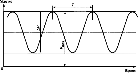
Figure D.1 – Designations for the parameters of the repeated load
D.3 The tests are carried out on test equipment (pulsators) with control of forces at the frequency of application of the load f from 1 to 200 Hz. Tests of each sample are continued up to 2 million cycles of loading or until the specimen breaks, which must be located along the length of the sample at a distance of not less than 2dK from the sample grippers (where dK is the nominal diameter of the reinforcing bar).
D.4 Reinforcing steel is recognized as meeting the requirements of this endurance standard if all test specimens are capable of withstanding 2 million cycles.
Appendix E (compulsory)
Determination of geometric parameters of the periodic profile of reinforcing bars
E.1 Actual values of the cross-sectional area and mass of 1 m length of reinforcing bars to control deviations of these values from the nominal values are determined in accordance with GOST 12004.
E.2 The diameter of the periodic profile is determined by means of a tubular gauge “passage is not a passage”
E.3 The height of the projections of the periodic profile is determined in the places of maximum height with the help of a measuring instrument (caliper, measuring microscope, etc.) of the required accuracy.
Bibliography
[1] “Cold Deformation. Prospects of cold-formed reinforcing bars “
Sergey Madatyan, Doctor of Technical Sciences, Professor, Head of the Rebar Laboratory, NIIZhB FGUP NIC “Construction”
Valery Bondarenko, Cand. Sc. (Eng.), Leading Researcher of the Rebar Laboratory at NIIZhB FGUP NIC “Construction”
“Metal Supply and Sales”, No. 4, April 2007
[2] GOST R 52544-2006 Rolled reinforcing welded periodic profile of classes A500C and B500C for reinforcement of reinforced concrete structures. Technical specifications
[3] RTM 393-94 Guidance technological materials for welding and quality control of joints of reinforcement and embedded products of reinforced concrete structures